K9AY Receiving Loop Antenna
I have an acre lot and that sounds like a pretty good size, but actually space for antennas is at a premium. The the house sits fairly far back on the lot and the lot is fairly long and narrow, almost a pie slice shaped, coming to a point in the backyard. Further complicating the issue is the arrangement of the trees that make for little room for low band antennas. I was able to squeeze a 40 Meter Double Extended Zepp fed with open wire feeders. Even in an Inverted VEE configuration it goes from lot line to lot line. It does a very good job on most bands, particularly 10 Mhz and below, I generally get pretty good signal reports but the antenna is noisy.
Non-resonant antennas tend to be noisier than resonant antennas, and dipoles tend to be noisier than loops, at least in my experience. This antenna confirms my experience.
K9AY Loop May Be the Answer
I have been looking for a good solution to the noise problem on receive and had heard about the K9AY loop antenna. It is a relatively small receiving loop that works well from 10 Mhz and down. I talked to with several hams about their experiences with the K9AY. N4IQ, Bill, is South Carolina was a great source. He has the K9AY and several beverage receiving antenna and had high praise for the performance of the K9AY.
When I saw a Array Solutions K9AY loop controller on QRZ’s swap page, I jumped on it. I had the controller in a week and started collecting the other bits and pieces for the loop. I measured off a space in one of the pine straw islands in the back yard. I found a good place to put it, but need to get some professional clean up of trees and low limbs. After the clean up the XYL was pleased with the the yard too. Little did she know what was coming!
What is a K9AY loop and why did I want one? The K9AY is a receiving loop antenna that works well on the lower frequency bands. It resembles a Delta Loop, but is a very good directional receiving antenna. Comprised of a 85 foot loop with a switching box located at the bottom feed point. Below is the basic K9AY Loop. You can click on the photos for a larger view:

Basic K9AY Loop Configuration
The loop is supported at the top, usually by a fiberglass pole, and fed at the bottom. One side of the loop is coupled to the feed line with an impedance matching transformer and the other side of the loop is returned to ground through a terminating resistor. This makes the loop directional in the direction of the feed line side, somewhat like a Beverage antenna. The K9AY now produced by Array Solutions, there are two loops, set at 90 degrees from each other and a control box with relays switches the feed and termination side of the loops.
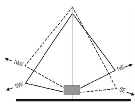
Setting the corners of the loops to the NW, SW, NE, NW directions and using the control box to select the proper feed and terminations gives a 4 directional antenna. The relays are controlled by a controller in the shack, that also includes a preamp. Since this is a small loop, there is a bit of loss of signal strength. The preamp helps bring the signals back up to about the same as a large antenna.
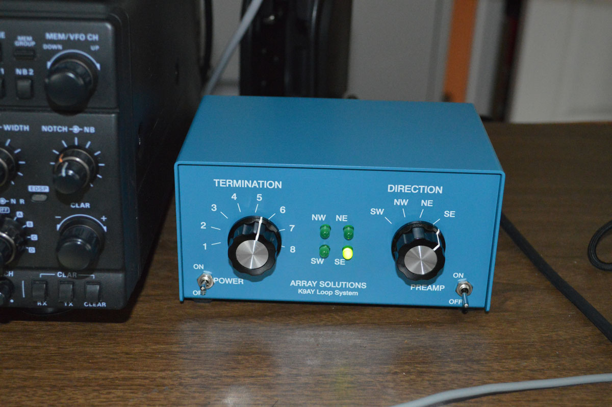
Array Solutions K9AY Loop Control
My K9AY Loop
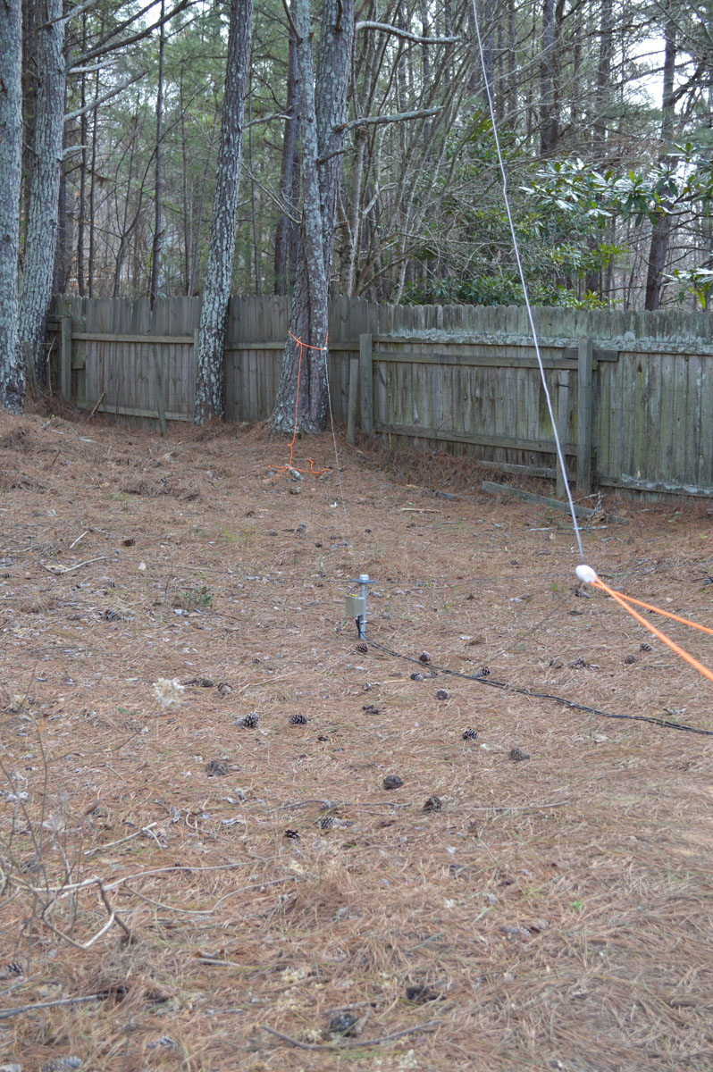
My implementation was to hang the top of the Loop from rope at strung between two trees in the pine straw island and then tie off the ends to stakes in the ground. At the feed point of the antenna there is a relay box. The relay box is a waterproof 4 inch electrical box with a plate attached that allows it to be mounted to a round post using a U-Bolt. I used a 30 inch section of 1 inch galvanized water pipe driven into the ground for the relay box mount. I made a strain relief / insulator for the loops out of a piece of 1/4″ PVC sheet. I cut a hole in the center that it would fit over the 1 inch pipe, and used a hose clamp below and a pipe cap on top of the PVC sheet. I drilled 4 snug holes in the corners to bring the loop wires through and wrapped them down to the relay box. I drove a 8 ft. ground rod beside the mounting post and tied the ground connection to the rod.

K9AY Base Detail Photo
To hold the top of the loop I made an insulator out of a small piece of PVC pipe with three sets of holes drilled through it. The top hole is for the support rope, another pair holes for the SW/NE loop to go through the insulator, and another pair of holes at 90 degrees from the first set for the NW/SE loop.
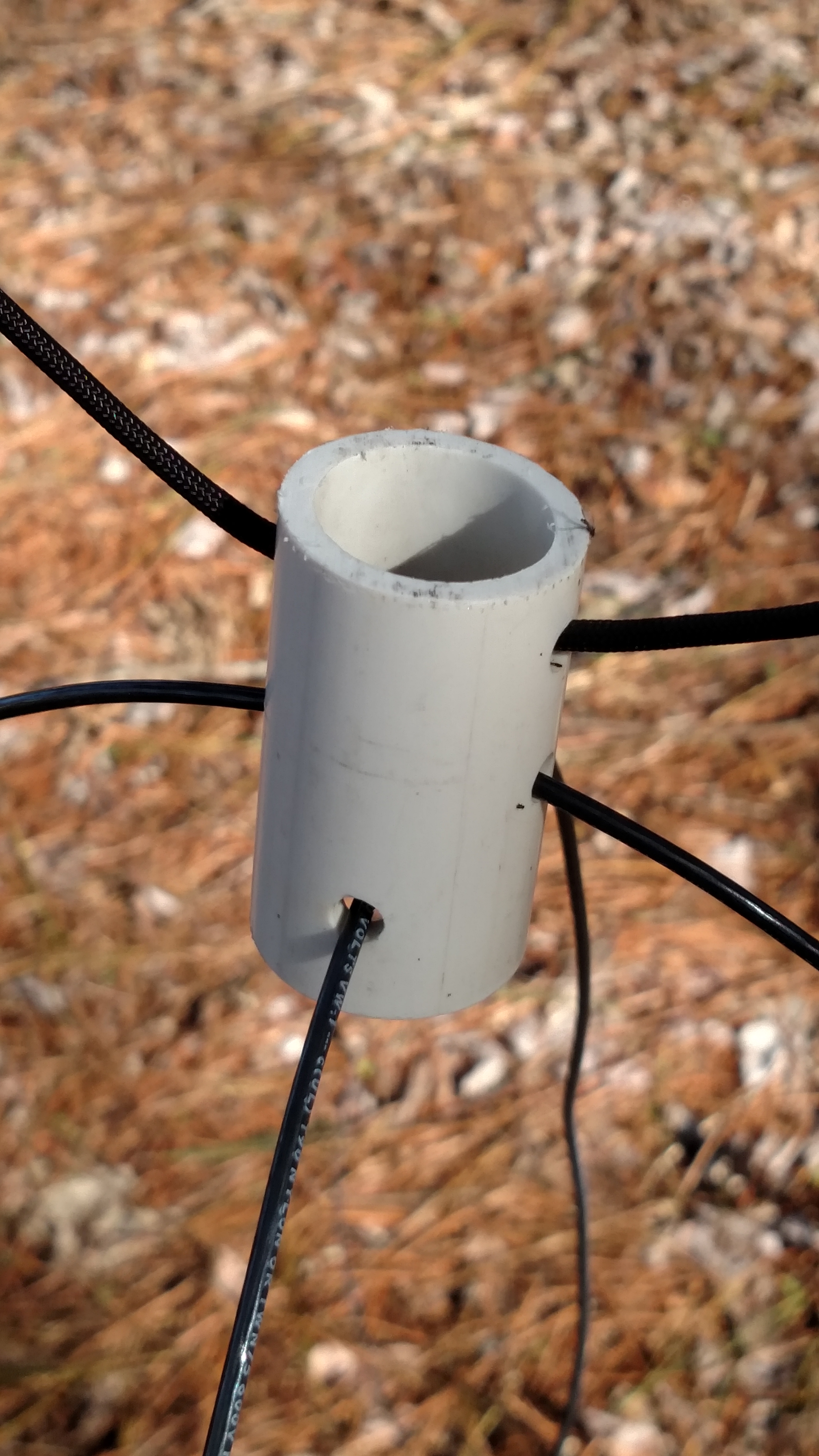
Top Insulator Detail
Finally, to hold then ends I used simple dog bone antenna insulator tied off to the ground stakes.
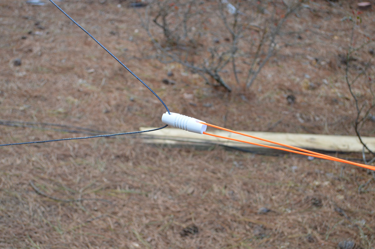
Dog Bone corner insulator
Ok, the ground stakes didn’t work all that well. Because the stakes were too close in from the center of the loop, the ends of the loop were too low. I just happened to have 4 trees that were off the ends of the loops, so I used some 1/8 inch rope around the trees at about 36 inches above the ground. That brought up the ends of the loops to a good height. It is hard to see, but in this photo looking across a loop, you can see the ends tied off to the trees.
Loop End View
Not that I was actually trying to hide this antenna, but with the black top rope and the black insulated wire for the loops the stuck back in the trees, the antenna is just about invisible from the yard. You can see the insulators and the florescent orange tie ropes for the ends, but otherwise it is very hard to see. If you are in a place that you have to hide your antennas, this arrangement will work great for a hidden antenna.
Results
I have had a few days now to work with the antenna. I love it! For some reason it is very noisy at my QTH. This antenna drops the noise level about 15 dB on 40 meters. My day for NCS on the Sunrise CW net gives me a good opportunity to evaluate the antenna. I can hear stations much better, and using the directionality of the antenna to reduce the noise and QRM I can copy stations much better than with the vertical or my Zepp.
I find that the loops pattern is a very broad front lobe with a very sharp notch off the back of the antenna. It works better at notching out a signal off the back of the antenna than bringing up a signal off the front. However, it still works very well. As you might expect, it doesn’t do much for very strong signals, other than notching them down off the back, but it will bring the noise down and the signal up on weak signals and make them very easy copy.
It works well on 160 meters through 40 meters, although the preamp in the Array Solution control box passband is about 1.5 to 4.5 Mhz, using it on 40 without the preamp works just fine. It also works very well on the AM broadcast band. I like listening to AM DX and this antenna works well. I have seen several instances when listening on US Clear Channel stations that I can switch the antenna to the SW or SE and completely notch out a US station and hear a Caribbean or Mexican station 599.
What now?
Well, other than wearing out the direction selector switch playing with the antenna, I have read that ground radials under the Loop Array improves the performance. So I will be getting some wire and put some radials under the array to see how that affects the performance.
Update
I recorded audio from the FT-1000MP on 40 meters switching between the K9AY loop and the inverted Vee antenna. From the recording you can hear the superior signal to noise ratio on on the K9AY compared to the Vee. The preamp in the Array Solutions control doesn’t cover 40 meters, so the signal strength drops a little, but the Signal to Noise ratio is still superior on the K9AY loop.
Great!!
I went to install one, but lightning damaged the resistors. I can’t see values. Can you help me??
Yes, here is the schematic of the remote box with the resistor values.
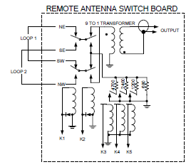
This is a common problem with powerful transmitter used near the receiving loop, the RF Power blows the termination resistors.
DE N4RFC