Vintage Radios and Modern Headphones
I have a number of pieces of “Vintage” Amateur Radio equipment that I have collected, repaired, and use regularly on the air. A lot of my time on the air is on CW, or Morse code for the non ham readers out there, and I use headphones to copy weak CW signals from time to time. Vintage headphones are not particularly comfortable to use and are hard to find and every harder to restore. So I wind up buying modern stereo headphones to use on my newer equipment and also on these older tube type radios. That creates a problem. These older radios are not the quietest things you want to hook to a pair of stereo headphones that have a wide frequency response. There is high frequency hiss noises created in the tube circuits and 120 Hz hum from the unregulated power supplies. Where modern amateur radio equipment has electronically regulated power supplies providing ripple free voltage for the circuits these older radios typically have a transformer with a full wave rectifier and high voltage filter capacitors to try to remove the ripple from the power that feeds the audio circuits. That produces a small amount of hum in the speaker that becomes not so small when you connect a set of headphones to the radio. So, what has that got to do with stereo headphones? Well, first off they are stereo. The older radios are all monaural, so some sort of plug in adapter is required to bridge right and left channels of the stereo phones to the monaural radio. Second, there there is the hiss and hum, particularly the hum being a problem for me. Modern stereo headphones are designed for very flat frequency response from below 50 Hz to 20,000 Khz. I don’t want to be hearing all that directly coupled 120 Hz hum from my Drake 2-B into my new Koss headphones!
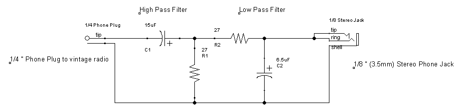
I hit upon the idea of putting a small audio passband filter in a 1/4 phone plug and build a passive filter for this application. I cracked the books on basic filter design and came up with this circuit:
Click on the graphic to see a larger image
A passband filter is comprised of a Low Pass Filter and a High Pass Filter in series between the input side and the output side. In this case I selected a low cutoff frequency of 400 Hz and a high cutoff frequency of 900 Hz. I usually tune in CW signals at around 600 to 700 Hz so that makes the filter just right for CW work. Since these are R (resistance) and C (capacitance) filters, I wanted to keep the resistor values low in this low impedance circuit to keep the loss of signal down. Using the formula:

I selected 27 ohm resistors and calculated the capacitor values and then rounded them to standard values that I had in my parts box to get the circuit shown above. The caps came out to be 6.5 microfarads for the Low Pass Filter and 15 microfarads for the High Pass Filter.
Not only did I want filter the audio I needed to convert from the typical 1/4″ Headphone jack that was used back in the day to a 1/8″ Tip/Ring/Shield that is commonly used on modern headphones. I hit my local Radio Shack’s parts drawers and found a very old school 1/4″ plug that had a big fat pull handle on it. It would give me plenty of room for my R/C components inside. I did a bit of trimming on the ground side of the plug to give me a bit more room for the components, and everything fit nicely into the handle. Here are a couple of pictures of the results:

Finished Filter Adaptor

Assembled Components
The results were quite good. The hiss and hum is reduced by a considerable level making the copy of weak CW signals much better and reduces my fatigue by not having to listen to quite loud hum through the headphones. All in all it was worth while project for a afternoon where it was too hot to do much outside!
I recall a similar idea in the Handbook, back in the 70s, and it made me reluctant to use good headphones on a radios until a few years ago. Their circuit used “88mH toroids” , which were telephone surplus (I think). They used those coils in everything back then. It would never fit in your headphone plug.
I probably would have gone with an active filter, but that’s just me.
You are right, they used those 88mH toroids for everything back then. I have a couple of them in the junk box. They are in a RTTY filter that I built years ago to use with the R-390A receiver. That goes back a while! The RTTY filter is a bandpass filter with a low pass and high pass L/C filter.
An active filter would have been good, but they you have to power it, and that gets messy on a headphone plug too. So, I figured there was enough signal from the headphone jack no the 2-B to overcome the loss in the R/C filter and I was correct. I have to advance the AF Gain on the Drake 2-B just a bit when going from the speaker to the phones and all is fine. It really does clean up the hum from the 2-B. I thought that when I re-capped the 2-B the hum would go away, and a lot of it did, but not all of it. The filter takes care of what was left quite well. Also works well on the R-4B.
Except for the fat 1/4 Phone Plug it was all junk box parts. Tantalum caps and 1/8 watt resistors from the CPI floor sweepings bucket. I still have a cigar box full of those parts that were dumped in the bucket back by the wave solder machine!