Heathkit HP-24 Re-cap
One of my favorite Heathkit products over the years is the HA-14 Compact Kilowatt amplifier. I had one back in the ’70’s. I used in at the home QTH with my Atlas 210. I had the mobile supply and I used it in the mobile with the Atlas. For the time the Atlas was the smallest HF transceiver around. The pair made a nice mobile station, running about 600 watts output in the mobile. But, I got away from mobile HF rigs in the car and didn’t use the HA-14 much. At some point I was downsizing the shack and I sold the HA-14, the AC and DC power supplies.
About 15 years ago I purchased another HA-14 and AC supply at a ham fest. I used it when I was moving around a lot relocating from Florida to Georgia. It makes a great portable amp. The HA-14 and its AC supply the HP-24 were manufactured in the middle ’60’s and only for two years. That means the electrolytic capacitors in these units are nearly 50 years old now. They are well past their peak! I have replaced the caps in my Drake 2B, my R-4B, and the AC-4 for the T-4xB. So, since I have all these old radios I have been replacing lots of caps lately, why not upgrade the caps in the HP-24 power supply. This is a photo essay on how I replaced the caps in the HP-24, the AC power supply for the HA-14.
50 years has surely changed electrolytic capacitors. The old style can electrolytic caps are just about unobtainable today. So you are left with the choice of using PC board mount caps, axial leaded caps, or if you’ve got lots of disposable cash, there are always the custom remanufactured cans. I have used the reman cans in my Drake 4 twins, but in that case I was trying to maintain the value of those old rigs by keeping them as original as possible. In the case of the HP-24 I was less concerned with the value and more with the function. So I decided to go with a snap in PC board mount electrolytic. They were about $4 from Mouser.com. The original caps were 125 mF at 450 VDC. Browsing Mouser.com I found a 150 mF snap in that was 1/4 the size of the originals. So there would be plenty of room for the new caps. Here is a photo of the original 125 mF 450 V can beside a 150 mF 450 V snap in from current production.
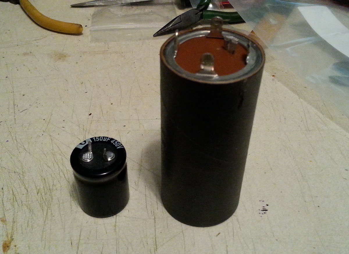
Old and New Electrolytic Caps
Of course, to start with you need to get the old caps out. Just in case you have an open bleeder resistor, carefully short the HV output terminal to ground to discharge any caps that may still have a charge. As old and leaky as these caps are by now, this is probably not necessary, but I just hate nasty surprises with high voltages! Start by removing the top cover, bottom cover, then remove the two screws that hold the diode board under the chassis. The diode board is mounted on two phenolic stand offs below the caps. You will have to unsolder the green wire from the top of the diode string that goes to the HV terminal to fold the diode board back out of the way.

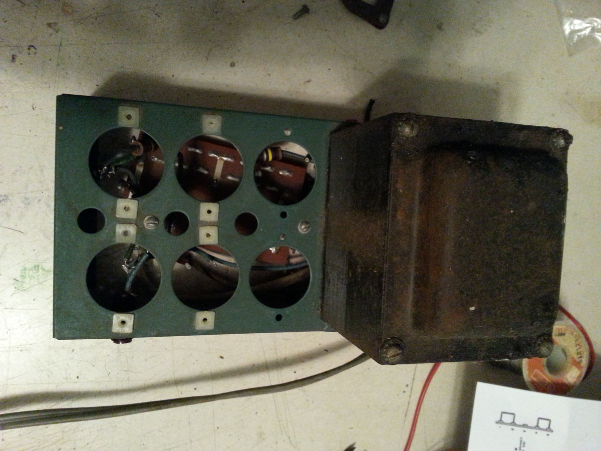
The original 50 year old wiring
With the diode board moved, you can see the original capacitor wiring. That wire coming from the transformer with the extra tubing on it goes to the center point of the six caps that are in series. Unsolder that lead and pull it back out of the way too.
Remove the 100K ohm resistors, wiring, and finally the caps. Un-solder any of the wires that are attached to the caps. Unscrew the phenolic mounting tabs with the cans attached. Once the caps are out you will see there are nylon inserts that the phenolic mounts were screwed into. I suspect these were used to increase the insulation and spacing on the higher voltage end of the capacitor string.
Chassis with caps and wiring removed
Pry the nylon screw mounts out of the chassis with a flat blade screwdriver.
I used a 4.5 X 6.5 piece of FR-4 perf board with a .1″ pattern of .062 holes to mount the caps. I trimmed the perf board down to just cover the can cap mounting holes up to about 1/8 from the edge of the chassis. As mentioned above, I selected a Snap In type electrolytic that had .062 wire leads which allows the caps to snap tightly into the perf board. Trim the board to fit over the original capacitor mounting holes without over hanging the chassis top. Mark and drill the perf board where the two screws for the diode board standoffs, and use those screws to mount the perf board to the metal chassis. The chassis should look like this when you are finished:
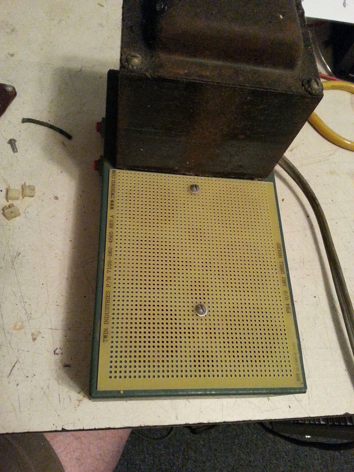
Prepped Chassis
Snap the caps into the perf board centering them in the original capacitor holes in the metal chassis and orient the leads so that you wire the caps in series starting at the ground near the corner of the transformer and positive leads so that the caps can be wired in series from the ground at the corner of the power transformer, to the last positive terminal near the HV connector.

Note the orientation of the negative sides of the caps
Start with the 100K 2 W resistors. I replaced the originals with some new metal film 2 W units from Mouser.com. Form the leads and J-hook them on to the caps leads. A small solder join will help old them in place while you complete the wiring. Small solder joints! Don’t over do it or it will be hard to J-hook the wires on to the small leads on the caps.
Then wire the caps together. I used solid wire so that I could dress the wiring away from the metal (grounded) chassis. Daisy chain from the positive of one cap to the negative of the next.

Lift the reistors up away from the Perf Board
Pay attention to the routing of the wires, keep them away from the grounded chassis.

This is what it should look like when you are done wiring
Replace the 40 uF bias supply cap on the diode board before you screw it back down to the standoffs. Connect the red-yellow wire from the transformer (with heavy tubing insulation) to the positive side of the third capacitor. Then put the diode board back into place and make the final connection from the diode board to the HV connector.
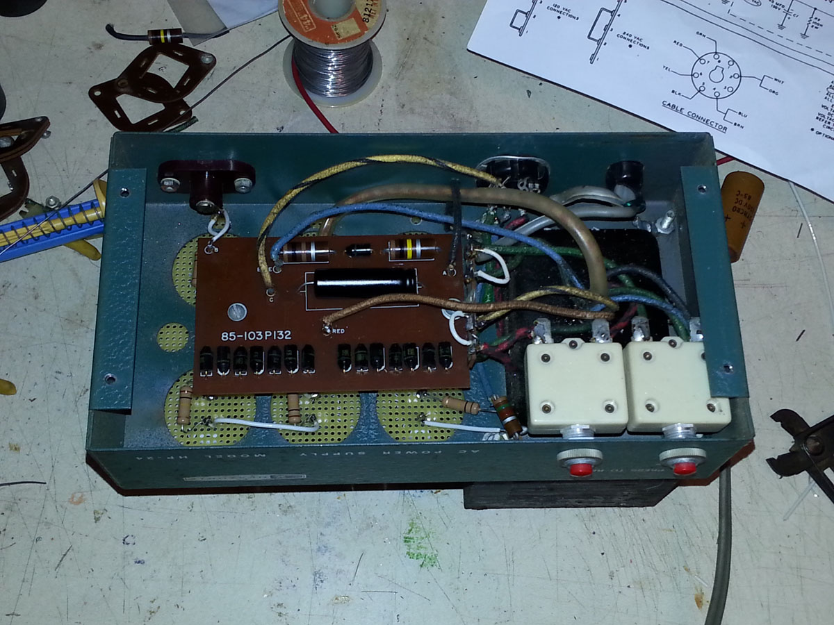
Completed wiring with diode board in place
That’s it….you’re all done. Recheck your wiring against the Heathkit assembly manual if you have it, or the schematic if you don’t. Be careful if you are going to test the supply before putting back in service. This supply puts out lethal voltages, lethal to you and to your test equipment. I didn’t have a voltmeter that would go to 2500 Volts. I tested the supply by measuring the voltage on the ALC Threshold output and doing the math on what the output voltage should be. The ALC Threshold is developed across a 1500 ohm resistor that is in series with the first 100K bleeder resistor. There are six 100K resistors, so that would be 600,000/1500 = 400, so the output voltage will be 400 times the voltage measured at the ALC Threshold. In my case it came out to 2520 Volts with no load on the power supply.
Here is a bill of material for the HP-24 re-cap process. I will list the generic part and the Mouser part number. I have been using Mouser for years and they have a good selection, quick shipping, and reasonable prices on small quantities of electronic components.
6) 150 uF, 450v, 20% .062″ Snap In Pins, AL Electrolytic Capacitors Mouser P/N 598-SLP151M450C3P3 (HV Supply Caps)
1) .1″ Grid, .062″ holes, 4.5″ X 6.5″ FR-4 Perf Board Mouser P/N 589-7100-062-4565 (Perf Board for mounting Caps)
6) 100K ohm, 2w Metal Film Resistors, Mouser P/N 588-ON1045E-R65 (bleeder/divider resistors)
1) 40uF, 150V, 20% AL Electrolytic Capacitor Mouser P/N 75-TVA1413 (bias supply cap)
Some folks asked about a schematic for the HP-24. I have a pretty decent copy….as with all the photos on this site you can click on the thumbnail below and see the full size schematic.

Great article!! I have HP-24 coming in the mail tomorrow and I plan to bring it back to life!!
Good job.
I may call harback for dimensions to see if i can could slip their board in it’s place, or close to it, otherwise, mine need replacing as they are likely the orginals as well.
I have had my HA-14 for 30yrs, and quit using it 15yrs ago with soft tubes, or at least I think.
I discovered the Pa0fri site, and my try his tube immisivation technique, just to be sure my T160l’s really need replacing. I have jig set up here to see how much current the old tubes have left in them. When I shelved it, it was only doing 310ma at around 2kw. One tube was slightly red, the other more orange. Could also be a resistor issue, but checking those tubes would eliminate one part of trouble shooting. I really don’t want to buy new tubes unless I have to, as they are pretty spendy.
I also have a few of those russian triodes ie, Gi7BT’s. I considered putting one of those in their place, then use the same hole that the sensitivity meter pot on the face of the amp is located, for a mounting position for a loading capacitor. Then it would look the same, but instead have a pot control would have a loading cap. with same knobs etc.
I think it would be a relatively easy conversion, as 12v for Gi7b filament already there, and the tank circuit, looks to have just about the same inductance values sufficient to resonate the tank using one of those tubes. The voltages on the HA are perfect for the Gi7’s too.
Just considering it mind you, or may just leave it the way it is.
73
warren
I recently purchased an HA-14 Amp with the HP-24 power supply. I have a Harbach SS-100-120/240 Universal Soft Start Module I would like to install, but I do not have a readable schematic or instructions on how/where to properly install it on the HP-24.
Are you aware of any detailed instructions, photos, videos and schematics that may be available? Thank you sincerely for any assistance you can provide.
De N4PIE
Tom,
I put a copy of the schematic I have on the page. Hope that helps. I would put the soft start in series with the power switch. That way it will work for both 110V and 220V settings.
Regards,
Bob – N4RFC
I really like your blog.. very nice colors & theme. Did you make this website
yourself or did you hire someone to do it for you? Plz
respond as I’m looking to create my own blog and would like to know where u got this from.
cheers
Yes, I built this myself, it is very easy to do with WordPress software. They have lots of different themes to download and you can in most cases customize from there. Give it a try, you will enjoy it.
Regards.